WeTeamUp Terms: “Chip Load”


What’s “Chip Load”?

WTU Terms: Chip load

[Chip load]

Milling is a very dynamic process. As a milling tool advances through material, its cutting edges remove small chips of material every time it rotates. Chip load is the term used to quantify this action. It is the length of material that is cut by each cutting edge as it moves through the material. In effect, chip load is the measure of the load a milling tool endures during operation. A properly setup chip load is essential for quality milling results and tool life longevity.

Simple Chip load diagram

To calculate chip load, you divide the forward speed of the tool by its rotational speed multiplied by the number of cutting edges. Chip load = Feed rate/(RPM*# of cutting edges)

Interesting Details about “Chip load”: 

  • It’s controlled by your nesting (CAM) software.

    In most cases labs don’t have control over milling parameters used on their machines. Your nesting software uses a predefined milling strategy to calculate the file for the mill. The design of that strategy is what sets all the parameters for milling, including chip load. Over all, strategies are highly refined by your software reseller. However, in our industry materials and processes are constantly evolving. It’s important to work closely with your reseller to make sure you have the best strategies for your application.


  • It directly controls the amount of energy needed to cut the material.

More aggressive chip loads require the machine to exert more force on the material to cut it, and lighter chip loads require less force. The ideal chip load is a balance between tooling, machine power, and desired surface finish.

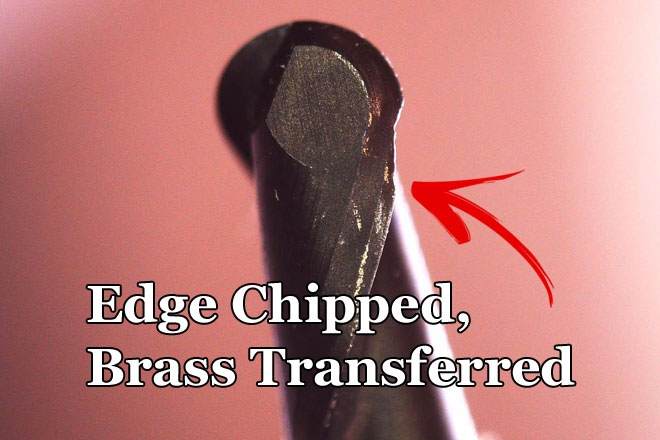
  • Chip load is directly correlated to tool wear.

There’s an entire science to this which is beyond the scope of this write-up. However, there’s a sweet spot for tool life longevity. Too light of a chip load and you’re scrubbing the tool through the material creating excess heat, abrasion, and wear. If your chip load is too high you run the risk of damaging the cutting edges of the tool and/or breaking it all together. It’s balancing act between material hardness, machine and tool capability, and the result you’re looking for.

  • It affects how fast your mill removes material.

The larger the chip, the more material the machine is removing at a time. It’s a common misconception that simply speeding up the feed rate will reduce milling times without consequence. Because rpm and feed rate both affect chip load equally, you should keep in mind that changing only one can have negative effects on you milling results and tool life.

  • Chip load affects the finish of your units.

If you have a good machine and good tooling, you should have good surface finishes. If you’re experiencing lines, scalloping, or other undesirable surface issues it might be time to look at the strategy. The designer of the strategy usually adjusts the chip load to give a “decent” result and the shortest reasonable milling times. There are usually gains to be made in quality if you’re willing to give up speed.

  • Be aware of speed adjustments on your machine.

Many milling machines have a manual speed adjustment that you can change on the fly. It’s important to keep in mind that if you adjust speed at the machine, you’re changing the chip load. Typically, the speed setting at the mill only affects feed rate. If you want to maintain the balanced settings laid out by your milling strategy, rpm and feed rate need to be adjusted in proportion to each other. If you’re unhappy with your current milling results, it’s best to have the adjustment done at the strategy level.

Thanks for reading! We hope this break down of the term “Chip Load” has been of value. Stay tuned next week for another post like this!

 Check out the growing list of WeTeamUp Terms posts HERE


WeTeamUp Terms: “Axis”

WTU Terms: Axis cover image

[ˈaksəs] -Noun

What’s an “Axis”?

An “Axis” is an imaginary line around which a dental milling machine moves. The purpose of an axis is to provide a reference point for precise controlled motion of the milling machine. All CNC (computer numerical control) machines convert numeric commands into positions on a specific axis. All of the motion commands that a milling machine follows are based on an axis. As your milling machine runs a program, it is controlling each axis individually to create the movements required to mill your units.

Interesting Details about “Axis”:

  • There are two types of axes: Linear and rotational.

    • A linear axis controls all the straight-line motion of the machine. These are usually the X, Y, and Z axes. Typically, X and Y are assigned to left/right and back/front movements of the machine, and the Z axis is used for the up/down movements.
    • A rotational axis controls all the turning motion of the machine. Usually, these are called the A and B axis. Dental milling machines that have a 4th and 5th axis usually use A and B to control left/right rotation and back/front rotation.
  • Dental milling machines don’t all use the same orientation for their axes.

    For example: one machine’s X axis may be another machine’s Y axis. The orientation does not affect the functionality of the machine, but it must be precisely represented by the CAM software to generate accurate commands. Commands designed for one type of machine will not work on another type. If a machine interprets a command for one axis on another the results can be quite bad, sometimes resulting in crashing and physical damage to the machine.


  • The more axes a machine has, the more complicated designs you can mill.

In dental milling machines you need a minimum of 4 axes to mill a crown. This is because the milling operations require X, Y, and Z movements, plus one rotational movement to flip the work-piece. When you add a 5th axis you gain another degree of positional control, thus allowing the machine to “see” more complex shapes.

  • 4-axis vs 5-axis machines:

    4-axis machines are typically a bit cheaper to buy than 5-axis, so there’s a trade-off between acquisition cost and capability. As a rule of thumb, a 4-axis machine will get 80-90% of dental restorations milled. If you’re a small lab doing mostly crown and bridge a 4-axis machine will get you there. 5-axis machines will allow you to mill pretty much anything. You can mill taller units in thinner pucks by rotating the design to fit. This can help you save money on materials. You can also mill more complex implant designs because the machine can “see” off-axis geometries and define them. If you’re in the market for a milling machine, consider these trade-offs before pulling the trigger.


Thanks for reading! We hope this break down of the term “Axis” has been of value. Stay tuned next week for another post like this!


Blog Series: WeTeamUp Terms

WTU-Terms-Intro

WeTeamUp is starting its new blog series “WeTeamUp Terms”

The new series will take a comprehensive look at terms that matter to those of us involved in dental CadCam.

Most of us reading this site are dental lab techs looking to become more knowledgeable. A good portion of our readership are new to dental CadCam, both technicians and lab owners alike. Starting off with digital can be a daunting task. WeTeamUp wants to try to alleviate that stress.

One of the most challenging aspects of learning dental CadCam is becoming familiar with the jargon. That’s how we came up with the idea for this new series. Over time, we will create a nice sized library of terms that will be an enduring resource for the digital community.

Every post we will pick a term that’s common in dental CadCam production and break it down. The posts will be easy to digest, quick reads that are 500 words and under. The idea is to be able to read a post within a few minutes and gain some insight, then go about your day.

Each post will be comprised of two sections. The first section will have a simple overview of that week’s term. Following that, the second section will be a bullet point list of interesting details to remember.

WeTeamUp terms has it’s own category, you can see all of the term posts HERE

We’ll also update a list of posts below:

Hopefully, we can teach you something along the way and improve your digital knowledge base.

Stay tuned!

WeTeamUp Terms: “Spindle”

WTU-TERMS_Spindle
WTU-TERMS_Spindle

What’s a “Spindle”?

[spin·dl] – Noun

The spindle is the business end of the dental milling machine. The term “spindle” refers to the mechanism that provides the power for the cutting tool. The spindle spins the cutting tool at high speed and supplies all the cutting force required for milling. If someone is talking about a spindle, they’re talking about the entire rotating assembly that holds the tool. This usually includes the spindle motor and tool changer mechanism.

Interesting Details about Spindles:

  • Spindles are costly wear items

Unfortunately, spindles wear out. It’s usually the costliest repair that we do on our milling machines. Depending on the machine they can cost up to $10k to replace. Be sure to consider this cost when you’re shopping for a milling machine. You can count on it coming up at some point – usually outside of the machines factory warranty.  To prolong the life of your spindle, make sure to maintenance your machine regularly.

  • How hard is it to replace a spindle?

The difficulty of the job varies from mill to mill. The cost of a service call to replace your spindle can be huge, and it’s on top of the cost of the part.  When you’re shopping for a machine ask if the spindle is user replaceable. On some mills, you can change it yourself in minutes. This can be a huge cost savings for labs willing to get their hands a little dirty.

  • The number one killer of spindles is bad compressed air

Most spindles utilize compressed air to cool their bearings. In fact, many of them run air directly past the high precision ceramic bearings. If the air is dirty or wet, it can corrode the bearings and greatly reduce the service life of the spindle. If your spindle is air cooled, it’s a must to invest in proper air filtration and drying.

  • Spindles come in all shapes and sizes

They can vary greatly in terms of power output. Some dental machines have as little as 100 watts of spindle power output, while others can range into the kilowatts. Spindle power output is correlated to machine cost. More power costs more. Machines designed to cut hard materials like titanium require much more robust spindles to get the job done. This is a major driver of the cost difference between desktop mills that are meant for soft materials and the more “industrial” breed of machines capable of milling hard materials.

  • Spindles and tool changing: Different schools of thought

Dental milling processes require several different sized tools to accomplish the job. Most dental milling machines utilize a tool changing mechanism that’s build into the spindle. Other designs use either multiple spindles or an externally mounted system. The way the manufacturer goes about this design decision impacts the cost and complexity of a spindle repair. As a rule of thumb, the simpler the better.

  • When the time comes: Rebuild or replace?

Many of the higher end spindles are rebuildable. You can save a major portion of your replacement cost by using a refurbished unit. If you utilize factory refurbishment, or the services of a reputable rebuild shop – the spindle will perform like new. If you’re a higher production lab, it might make sense to have a spare on the shelf ready to swap out. This move can save days of down time.

Thanks for reading! We hope this break down of the term “spindle” has been of value. Stay tuned next week for another post like this!

Roland Milling Bur Installation Tips

Goal: Avoid damage to the milling bur during installation

Loading burs into your machine is when you’re most likely to damage them. In this post, we’ll look at a few things you can do to avoid accidental damage to your Roland milling bur.

Many lab techs don’t know that the tip of a bur is delicate

The tungsten carbide that burs are made from is a very tough material. However, the shape of the material at the edge makes it susceptible to damage. The right impact can cause small defects in the cutting edge of your milling bur. These defects will drastically shorten the life of your bur. If you want to go in depth on that check out our post here: “Damaging Milling Burs: For Science!”

Roland milling bur install tips:

These tips apply to Roland DWX-50, DWX-51d, and DWX-52dc

  1. Be careful of the tip of the bur

Damaged Bur

It’s good to be generally mindful of where the tip of the bur is at all times. It’s easy to hit it on a variety of surfaces if you’re not aware of it. All it takes is one hit at the right angle to chip your bur.

  1. Load the collar shank first

Install Collars Shank Side First

When you are attaching the metal collar to the bur, always make sure you insert the bur shank (machine side) first. This way you avoid dragging the cutting edge of the bur across the metal collar

3. Gently lower the bur into the holder

Roland Milling Bur Loading

Once the bur is ready to insert into the machine’s holder, make sure that you center it in the holder before you push down. If it’s off center, it can hit the side or floor of the holder and damage the tip. Once it’s inserted, double check that it’s seated straight.

Conclusion

If you follow these simple tips when loading new Roland milling burs, you can reduce the chances of any damage happening to the bur. This is added insurance against early bur wear.


Damaging Milling Burs: For Science!

Damaged CAD/CAM milling burs will have a shortened life.

As a dental lab invested in digital technology, you want to get the most from your milling burs. Let’s take a look at what it takes to cause notable damage and how to avoid it. We’ll shed some light on the ways milling burs can get damaged and document the scope of that damage in each scenario.

It doesn’t take much damage to affect the lifespan of a milling bur.

The smallest defect in the bur’s cutting edge will become bigger as the bur wears. Any chip, divot, or abrasion in the bur will become a site for wear to propagate from. A damaged milling bur will work just fine for a little while, but it will certainly not last as long as a pristine one.

Accidents happen, so what’s the scope of the damage?

So, you dropped your bur… It’s probably fine, right? Unfortunately, there’s a good chance it sustained at least some damage. It all depends on how and what it hit. But how can you tell? To show you, I’m going to systematically destroy some milling burs and document the results.

How do burs get damaged in the dental lab?

I thought about the most likely ways for milling burs to get damaged in the lab. Here are a few that I came up with:

  1. Hitting a brass bur holder: It’s surprisingly easy to ding a bur when you install it in your milling machine.
  2. Hitting other burs: Are your burs rolling around in a drawer?
  3. Hitting the floor: Hard floors are not a bur’s friend.

How does each one of these affect the bur?

The only way to find out is to test it. I’ve designed a test to see how milling burs hold up to impacts with different materials. It’ll be interesting to find out how much abuse a bur can take before it’s got any visible damage. I’m going to do some controlled impacts of burs into various materials and show you what happens.

The Test:

The idea is to simulate an impact between a bur and these materials: brass, tungsten carbide, and tile – Then I’ll record what happens.

Building the Test Rig:

I needed to assure that the impacts to each material use the same force. After a little bit of research, I decided the best way to do that without fancy lab equipment was to build a simple pendulum. Using the same release point for the pendulum assures a reasonably accurate repeated force.

Test-rig-rendering 

Calibration:

The right amount of force is key. After much consideration, I decided to keep it simple. As a benchmark, I would use the force required to chip the lead on a freshly sharpened number two pencil.  I chose this because it’s easy to visualize and it’s repeatable.

I tested the pendulum rig with a pencil until the force chipped the tip. Then, I noted the mark that corresponds to that force.  That mark is used as the drop point for all of the tests.

Pencil-Force-Calibration-BEFORE


Pencil-Force-Calibration-AFTER

Results:


Test# 1: Bur hitting a brass holder

This one is designed to illustrate the impact between a bur and the brass holder in the mill. It’s easy to press the bur into the holder at the wrong angle or with too much force. It’s important to be diligent with your bur installations. Check out our post HERE for more on that.

#1-Tool-on-Brass-Holder-BEFORE

#1-Tool-on-Brass-Holder-AFTER

Notice the significant amount of edge damage. Not only is the diamond coating chipped, so is the carbide.  This is a fairly predictable result for a carbide on brass impact. This will surely affect the longevity of the bur.

Test# 2: Bur hitting another bur

This impact simulates a scenario where a bur hits another bur. This is most likely to happen if you store your milling burs lose in a drawer. We always recommend storing your burs in the original packaging or specialized bur holder. Check out our post on recommended bur care HERE

#2-Tool-on-Tool-BEFORE

#2-Tool-on-Tool-AFTER

This impact didn’t seem to dent the carbide very badly, but the diamond coating has certainly flaked off. Without the protection of the diamond coating in that area, this bur will surely suffer from a reduced lifespan.

Test #3: Bur hitting the floor

Here we’re testing an impact with the floor. We’re hitting a bur into a small piece of floor tile. The hardness characteristics of tile are much different than metal. Note: This may not be a perfect simulation of a floor drop because a tip impact from standing height would likely have a larger amount of force involved. However, in the interest of keeping the test fair, I’ve kept the force the same.

#3-Tool-on-Floor-Tile-BEFORE

#3-Tool-on-Floor-Tile-AFTER

This is by far the most interesting result. I expected somewhere between the carbide and brass tests. However, it appears to be at or greater than the damage caused by the carbide impact. This is definitely a reason to avoid letting your burs hit the floor!

Conclusion:

After running this test, it’s clear to me that any impact with a bur is not good. This is definitely something to keep in mind when you’re working with milling burs in your lab. If you do your best to care for your burs, you’ll insure you get the most bang for your buck.


Introducing WeTeamUp – Powered by Sierra Dental Tool

WeTeamUp is an educational and tech support resource powered by Sierra Dental Tool


Right to the point: Why should you subscribe to our blog?


Knowledge is power. At Sierra Dental Tool, we believe in empowering you. We want to scale-up our ability to do that. That’s why we’ve come up with the WeTeamUp blog. We want to team up with you – the dental lab tech in the trenches – to help you with the challenges you face every day. Here, we are going to answer the relevant questions. We are going to interface with you and bring the information you need.

Our goal is to help you, your lab, and your bottom line. If you visit on a regular basis, you’ll learn how to take better advantage of your equipment and improve your processes. Who doesn’t like higher productivity? It’s going to be worth the click.

What’s in it for us?

To be frank, all we want to do is spread awareness. There’s a growing trend in the dental lab industry. It seems that more value is being placed on short-term gains than long-term quality and service. That outlook doesn’t mesh with our philosophy. We’ve always been in it for the long haul, and today it’s no different. If we give freely to the industry now, down the road we might be known as the people who truly care. That’s good for everybody.

 Why should you value what we have to say?

Our staff has decades of collective experience in diamond/carbide tooling, machining, ceramics, and other industrial products. We entered the dental market over 10 years ago and we’ve built an excellent reputation in the industry. Our industrial background gives us a unique advantage over other dental tooling companies. When it comes to tooling, we know our stuff!

 Looking forward:

For us, the list of potential topics is vast… We’ve selected few we think might help to get started. We want to establish a baseline so we’re starting simple. Some of the first topics are: “Anatomy of a Tool: Understand the Parts” and “Tools Have Feelings Too – How to Treat a Tool Right” It’s important to us that we deliver the content that’s most useful to you.  Please be sure to interact with us on social media! (links in the top menu)  Tell us what you want to hear!

Sign up to stay up to date on our latest activity!

Anatomy of a Tool: Understand the Parts

In this post, we’ll give you a top-down view of the parts of a tool.

If you know the basic parts of the tool and understand some of the design variables, you can understand what you’re buying and make your dollars go further.

Overall Length: 

Measured end to end.

Nearly all of the dental CNC machines on the market today are designed around a very specific length of tool. All of the machining geometry is based on this dimension. It’s the foundation that the rest of your milling experience is built on. If the length is incorrect, trouble’s not far off.

Shank:

The thick part of the tool that is held in the spindle motor.

The quality of the shank determines how well it spins in the spindle. The finish tolerances set quality tooling apart from lesser tooling. Even the tiniest defect can cause an unbalance in the tool at speed.  Liken it to the rim on a bicycle. If you’ve ever tried riding a bike with a bent rim you can visualize the importance of spinning a tool precisely. You should also know that some manufacturers don’t make their own tools from start to finish. It’s common practice to buy inexpensive pre-made blanks and grind a design into it. That’s a great way to save money, but the trade-off is the risk of making a slightly bent bike wheel. It’s better to control the production of the tool blank in-house. Make sure you ask your supplier how they source and tolerance their blanks.

Reach:  

How deep the tool can mill.

While it’s nice to be able to mill deep pucks, longer isn’t always better. Longer reach makes the tool more susceptible to bending forces. As length is increased the tool is more likely to vibrate and break when milling. Labs are milling more larger pucks today. When using long reach tools, it’s important to counteract these tendencies with good strategy design. Whenever you make a change in your tooling the milling strategy needs an update as well. The tool needs to be represented correctly for the CAM software to generate precise tool paths. It’s common for this mismatch to cause tool impacts and breakages. Make sure you work with your tool supplier to avoid this issue.

Flutes/Cutting Edge Design:

The business end of the tool.

This part of the tool is directly responsible for the result you get from your mill. A good cutting surface will give you a good result, and vice versa. There are hundreds of different combinations of angles, profiles, and manufacturing processes that affect the performance of a tool in a given scenario.

If you look at the dental tooling market as a whole, you’ll find different schools of thought on how to design this part of the tool. On the low end, manufacturers can re-brand existing designs and sell them as dental tools. This practice is great for the profit margin on cheaper tools. Higher end manufacturers make the investment in good research and development. That gets you tools that are specially designed for the materials they are used in.  A well-designed cutting geometry will give you much longer service life, and improved surface finishes on your units.

Conclusion:

We’ve seen out-of-spec tooling cause a wide variety of problems. It’s a drag on productivity. As a lab tech your time is more valuable at the bench than chasing down problems with your Cad/Cam equipment. Don’t let tooling be the weakest link in your process. Use a quality milling tool and reduce your overall stress level while improving your bottom line.


Runout: Is it Chipping Away at Your Productivity?

In this post, we’re going to outline what runout is and what you can do to avoid it.

Runout is one of the most significant sources of milling problems in the dental lab. If you have ever had abnormal tool wear or strange breakages you can’t explain, there’s a good chance you’re experiencing the effects of runout.


What is runout?

Basically, runout is the tendency for a tool to wobble as it spins. Any time that the tool spins around an axis that is not its center, it’s running out. It might not seem like that bad of a thing, but the forces that are in play when a tool is cutting need to be in precise balance. If they’re not, the results are anything but ideal.


How does it affect milling?

Efficient milling processes are all about balance. When a tool is running out, its performance will degrade drastically. The main reason is that runout creates uneven cutting loads on the tool. As a tool runs out, the chip load (amount of material the tool cuts) on the tool is constantly changing. This causes uneven cutting stresses and wears the tool unevenly. Excessive runout will cause more tool wear, more chipping of margins, and more trouble overall.


What are the common causes of runout?

In an ideal world, the tool would be in perfect alignment with the spindle axis at all times. However, this rarely happens in real life. There are many variables involved in how precisely a tool spins.  Here are a few things you can check to help counteract the effects of runout:

  1. Collet health: The collet is responsible for centering the tool to the spindle. If it is worn or dirty it will easily cause runout. This alone is probably the largest contributor to runout related issues in the dental lab. All too often, the collet is ignored in the lab. It’s important to know that the collet is a wear item and does need to be serviced and replaced periodically. To avoid collet issues, make sure to follow the guidelines that came with your machine concerning collet maintenance.


  1. Tool quality: There are some low-quality tools on the market that aren’t made to the exacting standards that higher-end tools are. This results in a tool that can run out on its own. The ability to hold tight machining tolerances is the most important part of creating a quality tool. Just be aware: cheaper tools might have runout built right in.


  1. Spindle health: Unfortunately, spindles wear out. The bearings will wear and the spindle itself will start to runout. If the spindle is running out, so is the tool. Anyone who has run a milling machine for a significant amount of time will tell you that they’ve had to replace a spindle. It’s a huge headache, but if you’ve got a worn one you have to replace it.


  1. Milling strategy: Believe it or not, the strategy can cause runout too. The milling strategy tells the machine how to run the tool. It programs spindle speed, feed rate, depth of cut and other aspects of the milling process. If the strategy is not designed optimally, it can cause the tool to deflect (runout), and otherwise perform badly. In order to avoid this one, make sure you always have the most up to date milling strategy from your supplier.


How do you know if runout is your problem?

If you’re having milling issues there’s always a long list of potential causes. The best advice here is to work closely with your machine supplier and have them help you make the diagnosis. If you do have a runout problem, it’s likely you’ll go through several troubleshooting steps to get to it. This is because when troubleshooting a machine, the low hanging fruit is picked first. They’ll usually go through your software, calibrations, etc before attempting to diagnose a runout issue. Be aware that replacing tools or updating software may mask a runout issue short term, only for the problem to come back in short order.

If a runout condition is bad enough, it will show up in the tool wear pattern.  Look at the tool under the microscope. If it has more wear on one side than the other, it’s very likely that it has been running out.

The sure way to see if you have a problem with runout is to measure it. Some machines have indirect ways of measuring runout, but the most reliable way is to use a dial indicator and measure it right at the tool. Usually, this is something that a service tech will do on a field call. Every machine has a runout tolerance that is considered acceptable. If it’s outside the acceptable limits (ask your machine tech what these are) it will be time to replace the collet and/or the spindle on the machine in question.


Conclusion:

Regardless of what causes it, runout will erode your production efficiency. It will either creep up on you as your equipment wears or rear its ugly head suddenly. It’s best to be vigilant. Hopefully, you have gained a bit of knowledge about the characteristics of runout and increased your ability to troubleshoot on your own.


The Hidden Cost of Low-Priced Tools


The tooling that you select to support your CadCam workflow should be considered carefully. Tools weigh heavily on the quality and efficiency of your production process. It’s surprising that many labs don’t consider their tooling options thoroughly. In this post, we’re going to cover some of the things that you should be thinking about when looking at a tooling solution.

Tools Directly Affect Profitability.

The cost of tooling accounts for a big part of your cost to produce a zirconia restoration. It’s definitely worth looking at. When it comes to picking tools for your lab you have a couple of options: One is to choose inexpensive tools and save money on the purchase of the tools. Alternatively, you can spend more upfront on the tools and save money on your overall process.

The best way to quantify this is to look at your tooling cost per unit produced. Take a few minutes and calculate your milling tool cost per unit. The way you do it may vary, but usually we tell labs to figure it on a monthly basis. Take your monthly spend on tooling and divide it by your monthly unit production.

Now that you know where you sit, take a look at the example below and compare:


As you can see, the performance of your milling tools has a direct effect on your labs bottom line. It’s surprising to see how much can be saved per unit by spending more upfront on your tooling. If you’re still using lower yield tools it might be time to reconsider.

Better Tools Reduce Indirect Costs.  

Not only do good tools help your per unit cost drastically, they also reduce other costs around the lab.

  • One of the biggest ones is the reduction of internal remakes. When you factor in material, labor, and opportunity cost, the actual expense of a remake is incredibly high. If you can avoid a remake you should. Using long-lasting tools help you avoid machine related remakes because they will run many more units before chipping and other adverse results start to appear.
  • Good tooling reduces labor cost. There are labor savings in the reduction of remakes, repairs on milling related defects, and also less time spent changing tools out.
  • Premium tools are easier to your equipment. High-quality coatings and optimum cutting geometry reduce the cutting force during milling. Lower cutting forces reduce the wear and tear on your milling machine which helps you get more from your investment.

The Takeaway:

It’s always important to look at the big picture. It can be a mistake is to focus on the micro when you should be focusing on the macro. If you consider how each buying decision affects your overall system you always come out ahead.


Cleaning Milling Tools


Should I clean my milling tools?

In order for a tool to work at its peak efficiency, it needs to be clean. This is because as the tool cuts it makes a small chunk of material each time it spins around. When that chunk of material gets cut, it needs to get out of the way. There’s a short channel behind the cutting edge that gives the material a path to flow away. If you have too much build-up of material behind the cutting edge, it will keep the tool from moving material out effectively. Material build-up can cause the tool to re-cut material, which increases the wear rate of the tool and decreases the surface quality of the finished unit. Clean tools do run better.

How often should I clean them?

We recommend cleaning tools every 70-80 units and whenever you switch from one material to another. Some materials (i.e. high resin content wax and different brands of zirconia) will tend to stick to the tool more when milling. It’s important to remove that build-up to ensure the tool can perform properly.


How should I clean them?

We recommend using soap and water between the fingers, followed by an alcohol dip, then dry. Check out the detailed procedure below:

IMPORTANT: Do not steam clean diamond coated burs. The fast change in temperature can cause a thermal shock. We know it’s tempting… don’t do it.

Here’s our recommended procedure for cleaning milling burs:

What you’ll need:

-Water

-Soap

-Isopropyl alcohol

-Dirty tools

Step 1: Apply a small amount of soap/water on the tool with your forefinger and thumb. Gently work the soap mix into the tool to release material build-up.

Note: Be mindful of the cutting edge of the tool. If you handle it wrong it could cut your skin.

Step 2: Rinse the soap from the tool then look at it. If there’s still any visible build-up on the tool, repeat step 1.

Step 3: Dip the flute end of the tool in Isopropyl alcohol. This will remove any other residue left by the soap.

Note: It’s important to do this step! Left-over soap residue may encourage the material to stick to the tool when milling.

Step 4: Place the tool on a paper towel to dry.

Note: It’s important for the tool to be 100% dry before using again. Any left-over moisture can make material stick to the tool and may corrode other parts of the machine.

Note: If you choose to use compressed air to dry the tool (not recommended), be very careful not to send it flying.

Step 5: Get milling!


Conclusion:

Keeping your tools clean is an easy way to extend the life of your tooling and get better results from your milling machine. Add it to your process today and you won’t be disappointed.


Tools Have Feelings too: Some Best Practices for Tool Care

In this post, we’ll go over a few best practices for tool care.

The dental lab can be a harsh environment. There’s always a lot going on, and it’s easy to lose track of things. When it comes to tools you need them to be trouble free and reliable. While the large part of that reliability comes from using quality tooling, the other part is in your hands. There are a few things you can do to ensure the longevity of your tooling.


Storage:

Always store your tooling in its original packaging.

I’ve certainly been guilty of throwing a pile of them in a drawer to use later, but that’s a quick way to mess them up. If they bang into each other the cutting edges can be damaged. Damaged tools may still cut, but the life will be drastically reduced.


Cleaning:  

For a tool to perform at its peak ability, it should be clean.


We recommend cleaning tools every 70-80 units and whenever you switch from one material to another. Some materials (i.e. high resin content wax) will tend to stick to the tool when milling. It’s important to remove that build up to ensure the tool can perform properly.

Please check out our post on cleaning technique for more information.
HERE (link)

Handling:

When you’re holding a tool, always hold it from the shank (opposite the cutting) side.

Carbide is a great material to make a tool from. It’s very hard and long wearing.  Especially when it’s combined with a good coating. However, that doesn’t mean that the material is bulletproof. In fact, it’s much the opposite. Carbide is a very rigid material that doesn’t like to flex. Some of our dental tools are thin and fragile. Tools can be broken or damaged just by dropping them or even holding them incorrectly. I know I’ve ruined a few myself. Next time you have a spent tool in your hand (1mm or smaller) try to snap it in your fingers. You’ll be amazed by how easy it is.

Installation:

When you install a tool into your machine, be mindful of the tool’s cutting tip.

It’s easy to hit the tool’s tip on the tool holder when you are changing it out. Make sure you insert the tool straight down without hitting it on anything. Use the same mindset you would playing the game “Operation” — except don’t worry about the electrical shock.

Some machines require the user to install a metal collar prior to using the tool. Always install the collar from the shank first. That way you don’t run the risk of damaging the cutting edges.

Conclusion:

When you make the investment in quality tooling for your milling machine, you are investing in your own reputation. Good tools take care of you if you take care of them.