Tech Talk with Zahn: Part 2 “Ongoing conversation”

Greg Everette, Business Development, Sierra Dental Tool joins Andrew Kissin, Director of Marketing, Zahn Dental to discuss: – How diamond-coated burs compare to other burs in the market, i.e using a process called CVD – Sierra Dental Tool’s education and support website, WeTeamUp – Working with Zahn Technical Support to troubleshoot users


WeTeamUp Terms: “Tool Profile”

Tool-Profile-Cover

What is “Tool Profile”?

Tool profile is the shape of the tool’s cutting edge as seen from the side. As a milling tool shapes your part, it leaves a path that is the negative of its profile shape. The selection of tool profile is dependent on the type of milling that is being done. For instance, some shapes are better for 3d milling, while others are better for flat surfaces.

Interesting details about “Tool Profile”:

In the dental industry, there are only a few profiles that are widely used:

  • Ball: As the name suggests, this profile is shaped like a ball. These are the most commonly used tools in dental. Teeth are complicated shapes to mill. For this reason, we need a tool that can cut predictably from many different angles. Ball profile tools are best suited for this kind of 3-dimensional shaping. Ball profile tools leave a “scalloped” surface finish. To control this, you need to keep the scallops very small, which takes a considerable amount of mill time to achieve.Ball


  • Flat: Flat profile tools are used for geometries that need a flat surface. Most commonly they are used to define detail areas on implant-based restorations, such as screw seats and implant interfaces. Also, they are used when milling models to create smooth flat surfaces on the die and articulator seating surfaces.Flat


  • Toric: Toric profiles are flat bottomed, with rounded corners. They come in various diameters and corner radii. They are primarily used to do roughing of metals like chrome cobalt and titanium.Toric

Thanks for reading! We hope this break down of the term “Tool Profile” has been of value. Stay tuned next week for another post like this!

Check out the growing list of WeTeamUp Terms posts HERE

WeTeamUp Terms: “Calibration”

Calibration-Cover

[kal-uh-brey-shuhn]

What is “Calibration”?

Calibration is the comparison of values produced by a machine to a known standard of accuracy. Like any sensitive piece of equipment, modern dental CNC machines need to be calibrated in order to produce good milling results. All machines in our industry have some sort of calibration protocol. Usually, this involves milling a part of known geometry and taking measurements along the part’s surface. Those measurements are then compared to a set of known values, and the machine will calculate an offset value to compensate for any error.

Interesting Details about “Calibration”:

Follow your reseller’s recommendations

We can’t make a blanket statement on how often to calibrate because there are so many systems out there. However, your reseller will have a recommendation for you. These recommendations are minimums. You really can’t calibrate your equipment too often. It’s up to you to strike a balance between production and keeping up with the minimum recommended interval. There are a few reasons to calibrate more often:

  1.  You are a high production lab – the more miles you put on your machine, the more it will need upkeep.
  2. The machine is misbehaving – Margin chipping? Weird lines? The first step in any troubleshooting process should be a clean calibration.
  3. Your machine is in an environment with fluctuating ambient temperature – temperature swings will cause the machine to expand and contract, which can throw off the calibration. If your lab has temperature swings of more than 15-20 degrees Fahrenheit, you should calibrate more regularly.

Factory calibration vs user calibration

It’s worth mentioning that most systems have two separate calibration protocols. The first one you are probably familiar with, that’s the user calibration. The user calibration is simple, and easy to use. It gets the job done most of the time. For more difficult issues, the service personnel who work on your machine usually have access to a second, higher level calibration. This is more complicated but offers the technician far more control over the behavior of the machine.

Use the right tool for the job

The calibration of your machine is only as good as the measuring tool you use. Many people in our industry don’t consider this. It’s far too common to see a lab using a $20 digital caliper to calibrate their $100k machine. There are a lot of cheap calipers on the market, and you do get what you pay for. When you’re shopping for calipers look at two things: accuracy and repeatability. Low end equipment will not do well in either of these – typically they have an accuracy of +/- 0.02mm, and do not repeat very well at all. On the other end of the scale, you can’t go wrong with a Mitutoyo caliper. This one is accurate to +/-0.001mm and will repeat wonderfully.

Use good technique when measuring

The other aspect to consider when measuring your calibration part is technique. Poor technique will get you poor and unreliable results. We recommend these rules of thumb:

  1. Always zero your caliper before using it
  2. Measure using the same place on the caliper’s jaw every time. if you vary the surface used on the caliper, it is possible to introduce some error.
  3. Make sure that both the part, and calipers are clean before measuring.
  4. Don’t over pressurize the measurement. You can squeeze the milled part and produce an inaccurate measurement.

Sometimes you need to calibrate more than once

The further out of calibration that your machine is, the less likely it will compute perfect offsets the first time around. If you have a machine that requires significant adjustment to get close to calibrated, it’s good practice to calibrate again – until you get two repeated results close to ideal.


Thanks for reading! We hope this break down of the term “Calibration” has been of value. Stay tuned next week for another post like this!

Check out the growing list of WeTeamUp Terms posts HERE

WeTeamUp Terms: “Workholding”

Workholding_Cover

[wurk-hohl-ding]

What is “Workholding”?

Workholding is a term used in industrial machining to refer to an apparatus or device that holds the workpiece during machining. Its job is to securely and rigidly hold the material in place. We have workholding in dental, but most of it is figured out beforehand by your machine supplier or reseller. This includes any number of pre-made brackets or jigs that hold our pucks, blocks, and blanks.

Interesting Details about Workholding:

Rigidity is Key

The rigidity of a machine’s workholding setup is key to milling speed and accuracy. The higher the rigidity, the less the material can deflect when it’s under a milling load. Rigid setups allow the machine to mill faster and more accurately than a comparatively less rigid setup. The goal of any workholding device is to maximize rigidity while maintaining access for the machine tool to machine the part. This is a trade-off from an engineering standpoint. Most dental milling machines have managed to achieve a good balance between rigidity and material access.

It is Technique Sensitive

Like anything else in the lab, the way you work with your workholding setup is sensitive to technique. Uninformed users can easily cause adverse milling results Here are some common ones:

  • Alignment: You must align your material to the workholding the same way every time. If you don’t, you will mill your unit in an area that you didn’t mean to. This can cause material waste and badly milled units. Most milling systems have a suggested method to keep track of material alignment, it’s just an easy one to forget!
  • Torque: Nearly all the milling machines on the market require the user to tighten screws to operate the workholding setup. It is imperative to tighten the work holding hardware correctly. If it is over-tightened or unevenly tightened, you can damage your material. If it is under-tightened, the material might move during milling. This will cause a complete failure of the mill job and most likely a broken tool or two.

Thanks for reading! We hope this break down of the term “Workholding” has been of value. Stay tuned next week for another post like this!

Check out the growing list of WeTeamUp Terms posts HERE

WeTeamUp Terms: “Shank”

Shank-Cover

[shangk]

What’s a “Shank”?

The shank is the part of a milling tool that is held in the machine’s collet – opposite of the cutting end. The importance of the shank is often overlooked. It’s responsible for centering the tool in your machine’s spindle. A poorly made shank will make the tool wobble (runout) while it cuts. Runout is directly related to tool life, and the fit/finish of your units. The production quality of the shank directly affects the performance and longevity of the tool.

Interesting details about “Shank”

Critical reference point

The shank of the tool is a critical reference surface. The internal surface of the collet and shank must be precisely matched to ensure that the cutting end of the tool is concentric with the spindle’s axis of rotation. Any deviation from the spindle’s rotational axis will result in runout, which will reduce tool life and milling quality. The ideal shank is perfectly round and straight. If it’s not, it won’t clamp into the collet correctly and will perform badly. Well made tools control the roundness and taper of the shank to extremely tight tolerances (Sierra tools hold an H4 tolerance, suitable for aerospace applications).

Surface quality matters

The surface prep of the shank affects how securely it can be held during milling. Many tools on the market have a polished finish on the shank. While this is aesthetically pleasing, it degrades the performance of the tool because polished surfaces are slippery. Tools with polished shanks are not held as securely in the collet, which can cause tool slippage and poor milling results. Sierra tools have a matte “no-slip” shank surface that ensures proper clamping.

Cleanliness is important

Some dental machines are prone to tool slippage. You can help avoid this by keeping the shank and inside surface of the collet very clean. We recommend wiping both surfaces with alcohol to maximize the collet’s holding power.

Thanks for reading! We hope this break down of the term “Shank” has been of value. Stay tuned next week for another post like this!


Check out the growing list of WeTeamUp Terms posts HERE

WeTeamUp Terms: “Limit Switch”


Limit-Swtich-Cover

[lim-it-swich]

What’s a “Limit Switch”?

A limit switch is a device used to control the movement of mechanical parts. Dental CNC machines use several of these switches to operate various sub-assemblies. They are found in each machine axis, tool measurement probe, and safety interlocks. Limit switches are used to “tell” the machine’s control system where a component is relative to other parts of the machine. They are an integral part of your machine’s motion control system.

Interesting Details about “Limit Switch”:

How does it work?

Limit switches have two components: an actuator (usually a button or metal arm) and a set of contacts. When a part of the machine comes in contact with the actuator, the switch makes or breaks an electrical circuit which sends a signal to the machine’s control board. When the board receives the signal, it carries out a pre-set action.

CNC Axis

Most of the limit switches found in our machines are used in each of the machine’s axes. Each axis assembly has at least one. The “home” switch is located at the beginning of the axis range of motion. When a machine first turns on it goes through a homing sequence where it finds the limit switches on each axis. Once the machine is homed, it knows where each axis is in space. This location is critical, as all machine g-code commands are referenced from the home position.

Tool measurement probes

Many of the Tool measurement probes used in dental machines also utilize a limit switch. It’s a cost-effective way to measure tools, and the system works with enough accuracy for dental applications.

Safety interlock

One more area you may find these switches is inside your machine’s safety interlock system. Typically, there will be one or more switches employed in the circuit that tells the machine if the milling chamber door is open or closed.

Normally closed or normally open?

Switches can be wired to either open an electrical circuit or close an electrical circuit. If the switch is setup to open a circuit on contact it is considered “normally closed”, meaning that its default position is closed. If it’s setup to close a circuit on contact, it is “normally open”. This arrangement depends on the design of the machine.


Thanks for reading! We hope this break down of the term “Limit Switch” has been of value. Stay tuned next week for another post like this!

Check out the growing list of WeTeamUp Terms posts HERE

WeTeamUp Terms: “g-code”

GCode-Cover

[gee-kohd]


What’s “g-code”?


G-code is a text-based language that’s used to control all types of CNC machines. When your milling machine is running a program, it’s reading a g-code file with instructions that tell it where to move, how fast to do it, and what to do along the way. There are a few different types of machine code, but the term “g-code” is commonly used to refer to all of it. It can help to have a basic knowledge of g-code to expand your ability to self-troubleshoot and reduce reliance on outside support.


Interesting Details about “g-code”:

  • How it works:

Milling programs are generated by your CAM (nesting) software. The CAM software turns the 3d file of your unit into numerical g-code for the machine to read. The program can have thousands of individual lines of code. Each command line is based on a letter/number combination. The letter denotes the type of command, and the number indicates the command itself. The machine reads these commands line by line in sequence to carry out the milling program.

  • Some code breakdown:

Codes beginning with “G” are preparatory functions – they tell the machine to do a specific task, like setting work offset or telling it to move in a straight line to a given coordinate in space. M codes are miscellaneous codes. They are usually used to turn something on or off during the milling program, like compressed air, vacuum, or coolant. F codes are used to set the speed the mill moves at, in mm/min. S codes set the rotational speed of the spindle (RPM).

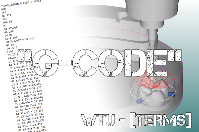
The example below is the beginning of a typical milling program.  Included are corresponding codes/actions – code in black, comments in [brackets] (code generated by SUM3d, for an Origin machine).


G90  [Absolute Positioning: all coordinates are referenced from the home (0,0,0) position]

G55 [This is the work offset. It tells the machine where “Home” for the given program is located]

M6 T1 [Machine to pick up tool #1]

M64 P3 [Vacuum on]

M7 [Compressed air on]

M3 S25000 [Spindle on, 25000 rpm]

G0 Z90 [Move to safety clearance position Z axis]

G0 A-180 [Flip the A axis over 180 degrees – this program starts milling on the bottom]

G0 X-3.997 Y-22.415 [Move to toolpath beginning position for the program X,Y axis]

G0 Z8 [Move to toolpath beginning position for the program Z axis]

G0 Z7.6 F900 [Move Z axis to engage the material, and start cutting at a feed rate of 900mm/min]

F2400 [Set feed rate to 2400mm/min]

G1 X-4.398 Y-22.404

G1 X-4.475 Y-22.429

G1 X-4.384 Y-22.476

G1 X-4.095 Y-22.514

G1 X-3.887 Y-22.489

G1 X-3.858 Y-22.461

G1 X-3.86 Y-22.456

G1 X-3.997 Y-22.415

G1 X-3.405 Y-22.495

G1 X-4.398 Y-22.404

G1 X-4.398 Y-22.404

[Now the machine is running the first tool. This stage will be followed by hundreds of lines of code that will guide the tool through space to shape the part. Each line of code represents a new point in space given in coordinates relative to the work offset. This operation will be followed by several more for each tool, which will eventually result in a completely milled unit.]


  • Codes used vary based on machine type, make/model.

Depending on the manufacturer of the machine, the code/language can be different. However, the principal is the same. If the CAM software and the machine are speaking the same g-code language, everything will work fine. For this reason, programs for one machine are not necessarily compatible with another machine.


Thanks for reading! We hope this break down of the term “g-code” has been of value. Stay tuned next week for another post like this!


 Check out the growing list of WeTeamUp Terms posts HERE

WeTeamUp Terms: “Air Blast”

Air-Blast-Cover

[ er blast ]


What’s “Air Blast”?

An air blast is a device that delivers a stream of high-pressure air to the tip of the milling tool while it is cutting. They are widely employed in both industrial and dental grade CNC machines. The purpose of an air blast is to remove debris from the milling tool while it is cutting. It’s very important to move debris away from the tool because it prevents re-cutting of material. A properly set up air blast is essential for efficient milling all dry dental materials.


Interesting Details about “Air Blast”

  • Why is it important?

Milling inherently creates waste debris and it needs to be removed effectively. As a milling tool cuts and creates this waste, it is possible for the waste to stay in the cutting area. If this happens, the material will be re-cut. Re-cutting material creates extra heat, abrasion, and load on the tool. The use of an air blast assures that this effect is minimized.

  • Improper setup can cause problems:

Issues with air blasts are a leading cause of pre-mature chipping and/or tool failure. If your air is not aimed or pressurized correctly, it won’t work. Your milling machine will still operate, but the extra heat and abrasion is hard on the tool. Without air, the tool is essentially scrubbing its way through the material. This can reduce the life of your tooling and cause non-ideal milling results. If you’re getting margin chipping or your tools aren’t lasting, make sure to check that your air is at the correct pressure and properly aimed.

  • They affect milling temperature.

To a minor degree, air blasts also serve to regulate the temperature of the milling tool as it is working. The cool, dry air removes heat directly from the tool through contact, and indirectly removes heat by evacuating waste material effectively.

  • The source matters:

The compressed air you feed your milling machine needs to be very clean and dry. Untreated compressed air contains moisture, oils, and particulates. These contaminates can cause adverse effects if they contact your restorations and can also contribute to pre-mature spindle wear. If your air is wet, it can cause certain materials to cake on the milling tool – which also reduces tool life. The investment in good air filtration and drying is certainly well worth it.


Thanks for reading! We hope this break down of the term “Air Blast” has been of value. Stay tuned next week for another post like this!


 Check out the growing list of WeTeamUp Terms posts HERE


WeTeamUp Terms: “Stepper Motor”

What is a “Stepper Motor”?

Stepper-motor-cover

[ˈstepər] [ˈmōdər]

A stepper motor is a special type of electric motor that is used in our dental CNC machines. These motors control the position of each of the machine’s axes. Stepper motors are different from regular electric motors because they offer extremely precise position control. Regular motors, while much more commonplace are only controllable in terms of rotational speed. On the other hand, stepper motors use a toothed rotor design in combination with a microcontroller to directly control the rotational position of the motor. This arrangement allows a computer to send a signal to the motor and tell it to move to or hold at any rotational position – with micron level accuracy.  This exact control is then combined with high precision mechanisms to create the CNC machine’s axis. Stepper motors are a key component in all the CNC machines dental labs use today.

Stepper-Motor-Mechanics
Belt driven CNC axis – stepper motor close up

Interesting Details about “Stepper Motor”:

  • How do they work? Stepper motors use toothed electromagnets to divide their rotation into equally distributed “steps”. They are controlled by an external circuit that produces pulse signals. The signals correspond to the relative position of the electromagnet and the motor’s rotor/shaft. This allows unique pulse signals to move the motor’s shaft to a fixed angle, thus providing the positional control needed.
Stepper-Motor-Apart
Stepper motor dissembled – Toothed electromagnet and rotor
  • They don’t require a feedback loop. One of the largest benefits of stepper motors over other means of mechanical control is that they do not need an external feedback loop to know where the motor is positioned. Stepper motors “know” where they are based on the input signal. This is especially useful in keeping the cost of our machines low because it simplifies the setup substantially.


  • There’s a huge variety available. Stepper motors are produced to meet nearly any industrial need. They are classified by the size of the frame and mounting bracket. The sizing standard is set by NEMA. This standard controls the basic size and shape of the motor, but not any of its other technical specifications. Motors are selected for their specific application and are not necessarily interchangeable based on size. The desktop dental machines that are common today typically use NEMA 17 or NEMA 23 sized motors.


  • They’re relatively inexpensive. They’re simple, and cheap to produce. Naturally, there is a variance in the quality from different manufacturers – so the price does range. However, cheap versions of the motors commonly used in our machines can be found online for less than $10 each.


  • Other applications in the lab? Anywhere there is a need for computer mechanical control, you’re likely to find a stepper motor. Around the dental lab, they are used in any CADCAM equipment that has moving parts. This includes all lab scanners and 3d printers.

Thanks for reading! We hope this break down of the term “Stepper Motor” has been of value. Stay tuned next week for another post like this!

 Check out the growing list of WeTeamUp Terms posts HERE

WeTeamUp Terms: “Yttria”


Yttria-Cover-image

What is “Yttria”?

[ih-tree-uh]

Yttria, otherwise known as Yttrium Oxide (Y2O3) is an additive used in all dental grade zirconia material. It is used to stabilize the zirconia during sintering.  As your zirconia restoration is sintered, it experiences a crystalline phase change. As the zirconia undergoes this phase change, it is inherently unstable. Without the addition of yttria, the zirconia we use would not have the properties needed for dental crowns.

Interesting Details about “Yttria”


  • Pure, unstabilized zirconia undergoes a phase transition from monoclinic (below 1170 °C) to tetragonal (between 1170 °C and 2370 °C) then to cubic (above 2370 °C). The use of a stabilization agent like yttria enables control of this crystalline growth. By changing the amount of yttria, we can control the strength and toughness of the final material.
  • The use of yttria in dental zirconia essentially “locks-in” the desired microstructure during sintering, thus allowing the correct crystalline phases in the material to develop. The stabilized zirconia has a much wider processing window, which allows multiple sintering temperatures and a reduction of the material’s sensitivity to variations in sintering process.
  • The concentration of yttria directly effects the strength and translucency characteristics of the zirconia material. Generally, the more yttria that is in the mix the more material will enter the cubic phase – resulting in more translucency and less flexural strength. This is why more translucent materials tend to be weaker.
  • “Zirconia” is a slang term. In the dental lab industry, when someone says “zirconia” it’s shoptalk for “Yttria Stabilized Zirconia”, or “YSZ”.

Thanks for reading! We hope this break down of the term “Yttria” has been of value. Stay tuned next week for another post like this!


 Check out the growing list of WeTeamUp Terms posts HERE


WeTeamUp Terms: “ATC”

ATC-Cover-Image

What is “ATC”?


“ATC” stands for “Automatic Tool Changer”. This one might seem a bit self-explanatory, but it shouldn’t go unappreciated.  An ATC is vital to the modern dental milling workflow. An ATC is responsible for picking up and measuring the correct tool for a given milling program. ATC’s simplify the milling process substantially. Without one, each tool change would need to be done manually. Milling times would be long and there would be much more chance for human error. With one, the milling process is automated down to a very simple level: Push a button, get a crown.

Interesting Details about “ATC”


  • Why do we need an ATC?

    To achieve the fit, finish, and accuracy we demand from our milling machines we need to use more than one tool. Milling processes used today start with a large roughing tool then work down to a smaller detail tool to do the finishing. Because of this, we need to change tools mid-program using an ATC.


  • Tool change time is a big part of your mill time.

If you’ve ever sat and watched your machine mill, you’ll notice that the tool change time can add up. Some machines can take more than a minute to change a tool. Keep this in mind when you’re balancing mill time and finish detail. The more tools you add to the milling process, the longer it will take. If you’re after fast mill times, it may make sense to remove the final detail (usually 0.6 or 0.3mm) tool to save time.


  • There are two types of ATC’s: pneumatic and electric.

They differ in the way they open and close the collet to pick up the tool. Pneumatic systems use compressed air and electric systems use an external motor. Some of the machines that use pneumatic systems are Imes-Icore, VHF, and Axsys. The most popular system using an electric ATC is are Roland’s DWX series. Both types achieve reliable results.

  • Parts of an ATC system:

    • Collet: This is the part that opens and closed to hold the tool in the spindle. It’s a very important part of the milling system. More on collets HERE.
    • Drawbar: This is a bar inside the spindle that is attached to the collet. It moves the collet in and out of the spindle while riding on the collet’s tapered surface. This action is converted into clamping force at the collet.
    • Measuring Switch: The mechanism used to measure the tool’s vertical position in the collet. Once the tool has been clamped into the collet, the machine will measure the tool’s tip on a known surface. This registers the tools length in the machine and enables it to mill accurate parts.


  • Having occlusion fit issues?

It might be your tool measuring switch. Every time the tool is picked up its length is different relative to the collet. The machine needs to know where the tools‘s tip is to mill accurate occlusions. A buggy tool switch can certainly cause high or low occlusions. To test this, mill the same design several times and see if the fit changes. If it does, you might want to contact your support supplier to investigate.


Thanks for reading! We hope this break down of the term “ATC” has been of value. Stay tuned next week for another post like this!


 Check out the growing list of WeTeamUp Terms posts HERE


WeTeamUp Terms: “Chip Load”


What’s “Chip Load”?

WTU Terms: Chip load

[Chip load]

Milling is a very dynamic process. As a milling tool advances through material, its cutting edges remove small chips of material every time it rotates. Chip load is the term used to quantify this action. It is the length of material that is cut by each cutting edge as it moves through the material. In effect, chip load is the measure of the load a milling tool endures during operation. A properly setup chip load is essential for quality milling results and tool life longevity.

Simple Chip load diagram

To calculate chip load, you divide the forward speed of the tool by its rotational speed multiplied by the number of cutting edges. Chip load = Feed rate/(RPM*# of cutting edges)

Interesting Details about “Chip load”: 

  • It’s controlled by your nesting (CAM) software.

    In most cases labs don’t have control over milling parameters used on their machines. Your nesting software uses a predefined milling strategy to calculate the file for the mill. The design of that strategy is what sets all the parameters for milling, including chip load. Over all, strategies are highly refined by your software reseller. However, in our industry materials and processes are constantly evolving. It’s important to work closely with your reseller to make sure you have the best strategies for your application.


  • It directly controls the amount of energy needed to cut the material.

More aggressive chip loads require the machine to exert more force on the material to cut it, and lighter chip loads require less force. The ideal chip load is a balance between tooling, machine power, and desired surface finish.

  • Chip load is directly correlated to tool wear.

There’s an entire science to this which is beyond the scope of this write-up. However, there’s a sweet spot for tool life longevity. Too light of a chip load and you’re scrubbing the tool through the material creating excess heat, abrasion, and wear. If your chip load is too high you run the risk of damaging the cutting edges of the tool and/or breaking it all together. It’s balancing act between material hardness, machine and tool capability, and the result you’re looking for.

  • It affects how fast your mill removes material.

The larger the chip, the more material the machine is removing at a time. It’s a common misconception that simply speeding up the feed rate will reduce milling times without consequence. Because rpm and feed rate both affect chip load equally, you should keep in mind that changing only one can have negative effects on you milling results and tool life.

  • Chip load affects the finish of your units.

If you have a good machine and good tooling, you should have good surface finishes. If you’re experiencing lines, scalloping, or other undesirable surface issues it might be time to look at the strategy. The designer of the strategy usually adjusts the chip load to give a “decent” result and the shortest reasonable milling times. There are usually gains to be made in quality if you’re willing to give up speed.

  • Be aware of speed adjustments on your machine.

Many milling machines have a manual speed adjustment that you can change on the fly. It’s important to keep in mind that if you adjust speed at the machine, you’re changing the chip load. Typically, the speed setting at the mill only affects feed rate. If you want to maintain the balanced settings laid out by your milling strategy, rpm and feed rate need to be adjusted in proportion to each other. If you’re unhappy with your current milling results, it’s best to have the adjustment done at the strategy level.

Thanks for reading! We hope this break down of the term “Chip Load” has been of value. Stay tuned next week for another post like this!

 Check out the growing list of WeTeamUp Terms posts HERE