What’s “Chip Load”?

[Chip load]
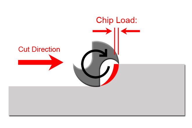
Milling is a very dynamic process. As a milling tool advances through material, its cutting edges remove small chips of material every time it rotates. Chip load is the term used to quantify this action. It is the length of material that is cut by each cutting edge as it moves through the material. In effect, chip load is the measure of the load a milling tool endures during operation. A properly setup chip load is essential for quality milling results and tool life longevity.

To calculate chip load, you divide the forward speed of the tool by its rotational speed multiplied by the number of cutting edges. Chip load = Feed rate/(RPM*# of cutting edges)
Interesting Details about “Chip load”:
-
It’s controlled by your nesting (CAM) software.
In most cases labs don’t have control over milling parameters used on their machines. Your nesting software uses a predefined milling strategy to calculate the file for the mill. The design of that strategy is what sets all the parameters for milling, including chip load. Over all, strategies are highly refined by your software reseller. However, in our industry materials and processes are constantly evolving. It’s important to work closely with your reseller to make sure you have the best strategies for your application.
-
It directly controls the amount of energy needed to cut the material.
More aggressive chip loads require the machine to exert more force on the material to cut it, and lighter chip loads require less force. The ideal chip load is a balance between tooling, machine power, and desired surface finish.
-
Chip load is directly correlated to tool wear.
There’s an entire science to this which is beyond the scope of this write-up. However, there’s a sweet spot for tool life longevity. Too light of a chip load and you’re scrubbing the tool through the material creating excess heat, abrasion, and wear. If your chip load is too high you run the risk of damaging the cutting edges of the tool and/or breaking it all together. It’s balancing act between material hardness, machine and tool capability, and the result you’re looking for.
-
It affects how fast your mill removes material.
The larger the chip, the more material the machine is removing at a time. It’s a common misconception that simply speeding up the feed rate will reduce milling times without consequence. Because rpm and feed rate both affect chip load equally, you should keep in mind that changing only one can have negative effects on you milling results and tool life.
-
Chip load affects the finish of your units.
If you have a good machine and good tooling, you should have good surface finishes. If you’re experiencing lines, scalloping, or other undesirable surface issues it might be time to look at the strategy. The designer of the strategy usually adjusts the chip load to give a “decent” result and the shortest reasonable milling times. There are usually gains to be made in quality if you’re willing to give up speed.
-
Be aware of speed adjustments on your machine.
Many milling machines have a manual speed adjustment that you can change on the fly. It’s important to keep in mind that if you adjust speed at the machine, you’re changing the chip load. Typically, the speed setting at the mill only affects feed rate. If you want to maintain the balanced settings laid out by your milling strategy, rpm and feed rate need to be adjusted in proportion to each other. If you’re unhappy with your current milling results, it’s best to have the adjustment done at the strategy level.
Thanks for reading! We hope this break down of the term “Chip Load” has been of value. Stay tuned next week for another post like this!
Check out the growing list of WeTeamUp Terms posts HERE

