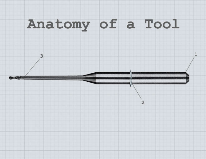
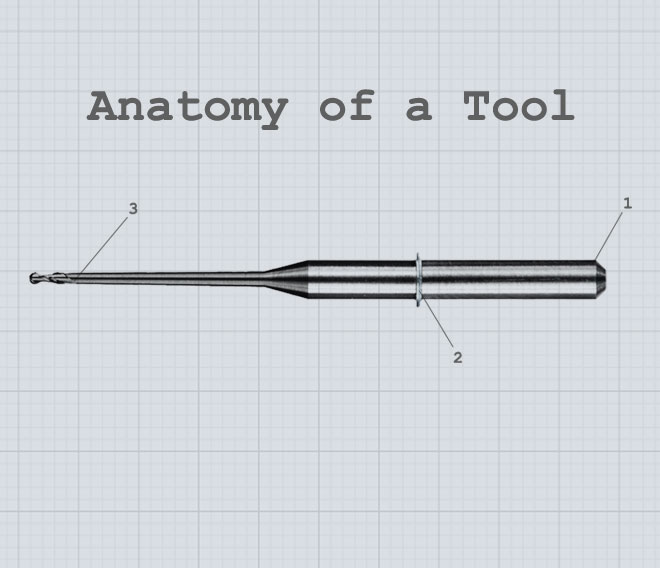
In this post, we’ll give you a top-down view of the parts of a tool.
If you know the basic parts of the tool and understand some of the design variables, you can understand what you’re buying and make your dollars go further.
Overall Length:
Measured end to end.
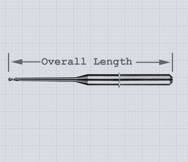
Nearly all of the dental CNC machines on the market today are designed around a very specific length of tool. All of the machining geometry is based on this dimension. It’s the foundation that the rest of your milling experience is built on. If the length is incorrect, trouble’s not far off.
Shank:
The thick part of the tool that is held in the spindle motor.
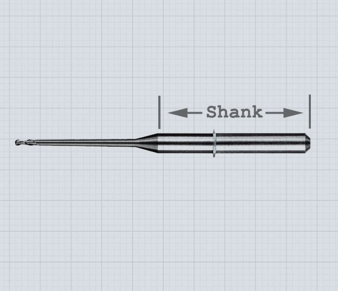
The quality of the shank determines how well it spins in the spindle. The finish tolerances set quality tooling apart from lesser tooling. Even the tiniest defect can cause an unbalance in the tool at speed. Liken it to the rim on a bicycle. If you’ve ever tried riding a bike with a bent rim you can visualize the importance of spinning a tool precisely. You should also know that some manufacturers don’t make their own tools from start to finish. It’s common practice to buy inexpensive pre-made blanks and grind a design into it. That’s a great way to save money, but the trade-off is the risk of making a slightly bent bike wheel. It’s better to control the production of the tool blank in-house. Make sure you ask your supplier how they source and tolerance their blanks.
Reach:
How deep the tool can mill.
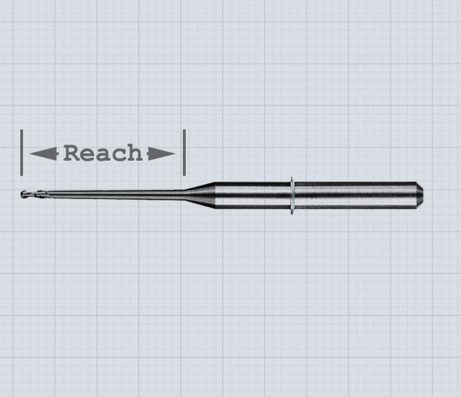
While it’s nice to be able to mill deep pucks, longer isn’t always better. Longer reach makes the tool more susceptible to bending forces. As length is increased the tool is more likely to vibrate and break when milling. Labs are milling more larger pucks today. When using long reach tools, it’s important to counteract these tendencies with good strategy design. Whenever you make a change in your tooling the milling strategy needs an update as well. The tool needs to be represented correctly for the CAM software to generate precise tool paths. It’s common for this mismatch to cause tool impacts and breakages. Make sure you work with your tool supplier to avoid this issue.
Flutes/Cutting Edge Design:
The business end of the tool.
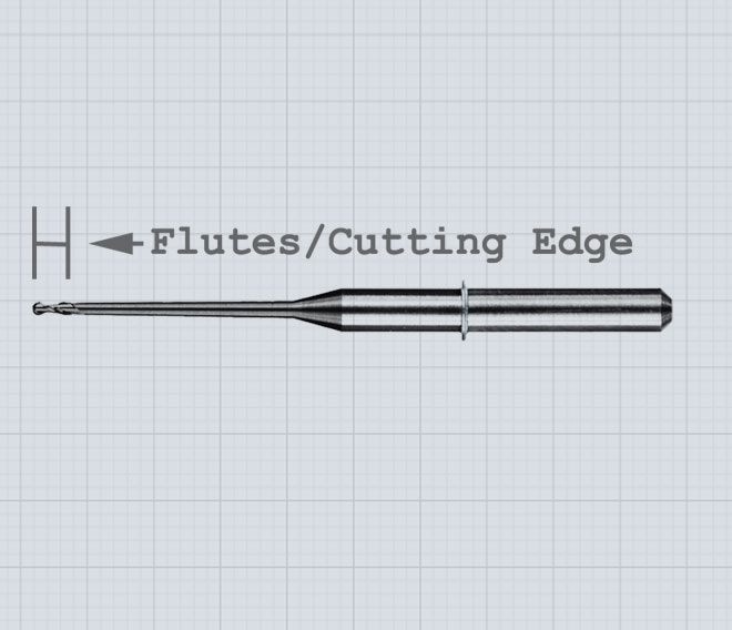
This part of the tool is directly responsible for the result you get from your mill. A good cutting surface will give you a good result, and vice versa. There are hundreds of different combinations of angles, profiles, and manufacturing processes that affect the performance of a tool in a given scenario.
If you look at the dental tooling market as a whole, you’ll find different schools of thought on how to design this part of the tool. On the low end, manufacturers can re-brand existing designs and sell them as dental tools. This practice is great for the profit margin on cheaper tools. Higher end manufacturers make the investment in good research and development. That gets you tools that are specially designed for the materials they are used in. A well-designed cutting geometry will give you much longer service life, and improved surface finishes on your units.
Conclusion:
We’ve seen out-of-spec tooling cause a wide variety of problems. It’s a drag on productivity. As a lab tech your time is more valuable at the bench than chasing down problems with your Cad/Cam equipment. Don’t let tooling be the weakest link in your process. Use a quality milling tool and reduce your overall stress level while improving your bottom line.